As a seafarer on a merchant ship or as a ship manager/owner of a vessel, one of the biggest nightmares is that of any kind of oil pollution accident from a ship.
A ship produces oil and water mixture on a daily basis which needs to be separated from each other, before discharging the dirty water out of ship using equipment such as oily water separator.
MARPOL has a regulation under ANNEX I which limits the oil content in the bilge water that vessel can legitimately discharge into the sea. It is now a requirement for all vessels to have an oil discharge monitoring and control system along with an oil filtering equipment known as the Oily Water Separator (OWS).
A ship engineer may work with 5-10 different makes of marine engines, but he/she is more likely to encounter many more types and makes of OWS in his/her career span. Even for PSC inspectors and surveyors, oily water separator (OWS) has always been a preferred choice of machinery on the ship for inspection. Hence, it is imperative to know and understand the basics of oil and water separator design and how an oil and water separator works.
As the name indicates, the function of oily water separator is to separate maximum amount of oil particles from the water to be discharged overboard from engine room or cargo hold bilges, oil tanks and oil-contaminated spaces. As per maritime regulations, the oil content in the water processed from the OWS must be less than 15 parts per million of oil.
Related Reading: What is Oil Discharge Monitoring and Control System?
Regulation for Oily Water Separator:
As per Annex 1 of MARPOL under regulation 4 specified under paragraphs 2, 3, and 6, any direct discharge of oil or oily water mixture into the sea shall be prohibited. The regulation further explains how an oily water mixture can be treated onboard and can be discharged out at sea:
Oil Water Discharge Regulation-
For a ship with 400 GT and above, discharge of oil mixture can be done under the following conditions:
1. The ship is en route;
2. The oily mixture is processed through an oil-water separator filter meeting the requirements of regulation 14 of this Annex;
3. After passing the oil-water separator system, the oil content of the effluent without dilution does not exceed 15 parts per million;
4. The oily mixture does not originate from cargo pump-room bilges on oil tankers
5. In oil tanker ship, the oil-water mixture is not mixed with oil cargo residues
When the ship is plying in the Antarctic area, any discharge into the sea of oil or oily mixtures from any vessel shall be prohibited.
Important Oily Water Separator (OWS) requirement:
- As per the MEPC 107(49), the bilge alarm or an Oil Content Monitors, which provides for internal recording of alarm conditions, must be certified by an authorized organization
- The OCM provided with the oily water separator must be tamper-proof
- The OCM must activate and sound an alarm whenever freshwater is used for cleaning or zeroing purposes
- Separator capable of achieving 15 ppm on type C emulsion
Construction and Working of Oily Water Separator (OWS)
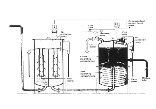
OWS consists of mainly three segments:
1. Separator unit
- This unit consists of catch plates which are inside a coarse separating compartment and an oil collecting chamber.
- Here the oil having a density which is lower than that of the water, which makes the former rise into the oil collecting compartment and the rest of the non-flowing oil mixture settle down into fine settling compartment after passing between the catch plates.
- After a period of time, more oil will separate and collect in the oil collecting chamber. The oil content of water which passes through this unit is around 100 parts per million of oil.
- A control valve (pneumatic or electronic) releases the separated oil into the designated OWS sludge tank.
- The heater may be incorporated in this unit for smooth flow and separation of oil and water.
- A heater may be incorporated in this unit either on the middle or sometimes in the bottom part of the unit (depending upon the area of operation and capacity of the separator equipment) for smooth flow and separation of oil and water.
- The first stage helps in removing some physical impurities to achieve fine filtration in the later stage.
2. The Filter unit
- This is a separate unit whose input comes from the discharge of the first unit.
- This unit consists of three stages – filter stage, coalescer stage and collecting chamber.
- The impurities and particles are separated by the filter and are settled at the bottom for removal.
- In the second stage, coalescer induces coalescence process in which oil droplets are joined to increase the size by breaking down the surface tension between oil droplets in the mixture.
- These large oil molecules rise above the mixture in the collecting chamber and are removed when required.
- The output from this unit should be less than 15 ppm to fulfil legal discharge criteria.
- If the oil content in water is more than 15 ppm then maintenance work such as filter cleaning or renewal of filters is to be done as required.
A freshwater inlet connection is also provided to the filter unit to clean and flush the filter. This is usually done before and after the operation of an oil separator unit.
3. Oil Content Monitor and Control Unit
- This unit functions together in two parts – monitoring and controlling.
- The ppm of oil is continuously monitored by Oil Content Monitor (OCM); if the ppm is high it will give an alarm and feed data to the control unit.
- The control unit continuously monitors the output signal of OCM and if alarm arises, it will not allow the oily water to go overboard by means of operating 3-way solenoid valve.
- There are normally 3 solenoid valves commanded by the control unit. These are located in the first unit oil collecting chamber, second unit oil collecting chamber and one in the discharge side of the oily water separator which is a 3-way valve.
- The 3-way valve inlet is from the OWS discharge, where one outlet is to overboard and the second outlet is to OWS sludge tank.
- When OCM gives an alarm, 3-way valve discharges oily mixture in the sludge tank.
A small pipe connection of fresh water can be provided to the OCM unit for flushing. Whenever this line is in use, an alarm is sounded and recorded in the OCM log, ensuring a record to check the discharge valve was shut during this period.
As in most of the shipping companies, the OWS is meant to be operated only by the chief engineer, the training levels on OWS systems for other crew members are found to be very low. The ship operators should ensure onboard guidance and training are included in the training schedule of the ship.
References
Introduction to Marine Engineering- By D.A Taylor
Comments
Post a Comment